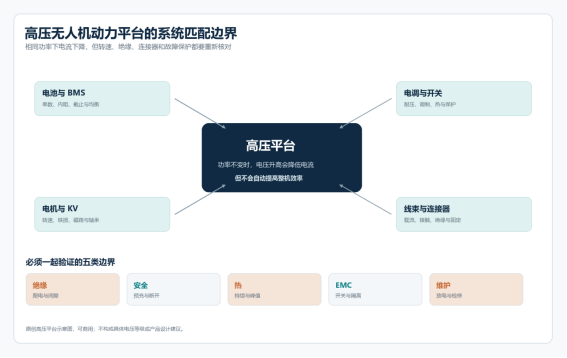
How to validate a UAV power system in heat and dust
From peak temperature rating to sustained mission capability. Environmental fitness is not one maximum temperature or IP rating. What decides field performance is whether the power system can shed heat under continuous load, keep particles out and stay serviceable.
Ambient temperature is not the only temperature variable
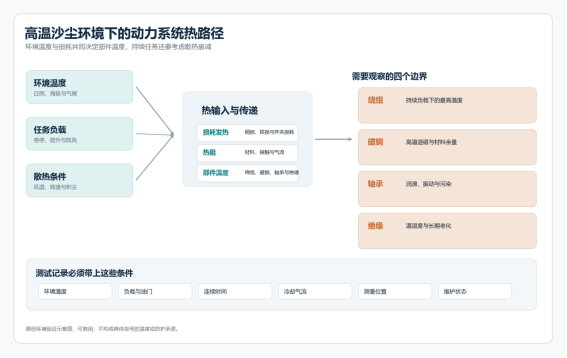
Datasheets quote an allowable ambient, but in the field what matters is the actual temperature of windings, magnets, bearings and insulation. Component temperature comes from ambient plus internal loss, with loss conducted out through thermal resistance. Raise ambient and internal temperatures shift up even at the same load, eating into the temperature-rise margin you thought you had.
A short peak test and a sustained hover test answer different questions. A peak run may last tens of seconds, before heat has spread through stator, housing and mount; a sustained mission may run for tens of minutes until temperature stabilises. If the system relies on prop wash for cooling, hover, slow climb and long ground runs offer completely different conditions.
A thermal test should therefore state ambient temperature, load and throttle, continuous or cyclic duration, cooling airflow, measurement location and whether thermal equilibrium was reached. A bare maximum temperature, without time and cooling conditions, tells a buyer nothing about whether it means momentary survival or continuous duty.
Dust changes cooling and maintenance first
When dust gets into motor and ESC, the first thing to change is rarely an electrical parameter — it is cooling and maintenance. Air paths between rotor and housing can clog, filter resistance rises as dust builds, and a insulating layer forms on heat-sink surfaces. To hold thrust the system then needs more RPM or current, pushing temperature higher still.
Bearings, connectors, encoders and sensors are more sensitive. Fine particles reaching a bearing can break the lubricating film, raising friction and vibration; dust inside a connector increases leakage risk in humid air; a fouled sensor window feeds the control loop bad data. Sealing only reduces the probability of ingress — it does not replace scheduled inspection and cleaning.
An IP rating is a type-test result, not a promise that no maintenance is needed at any dust concentration or service interval. Keep asking about seal design, filter change interval, bearing protection, drainage paths and cleaning method. For firefighting, inspection and emergency work the system must also be quick to check after landing, so servicing does not delay the next sortie.
Write environmental validation into the selection criteria
Environmental validation should start from the mission profile, not a single oven test. A test matrix can cover ambient temperature, altitude, solar load, dust concentration, payload, hover share and continuous run time, recording airflow path, filter and service state. Results are only comparable when conditions resemble the target market.
Acceptance cannot be “it still took off”. More meaningful data includes time to thermal equilibrium, spurious protection trips, insulation resistance drift, vibration growth, and wear on bearings, harness and connectors after the test. Protection logic and recovery steps after a fault are part of environmental capability too.
Suppliers should also provide derating guidance, a replaceable-parts list and inspection intervals. Buyers can compare options under one set of mission conditions and gradually align test results with after-sales records. One heat or dust test proves behaviour under one condition; continuous operation and service data show whether the system suits long-term use.